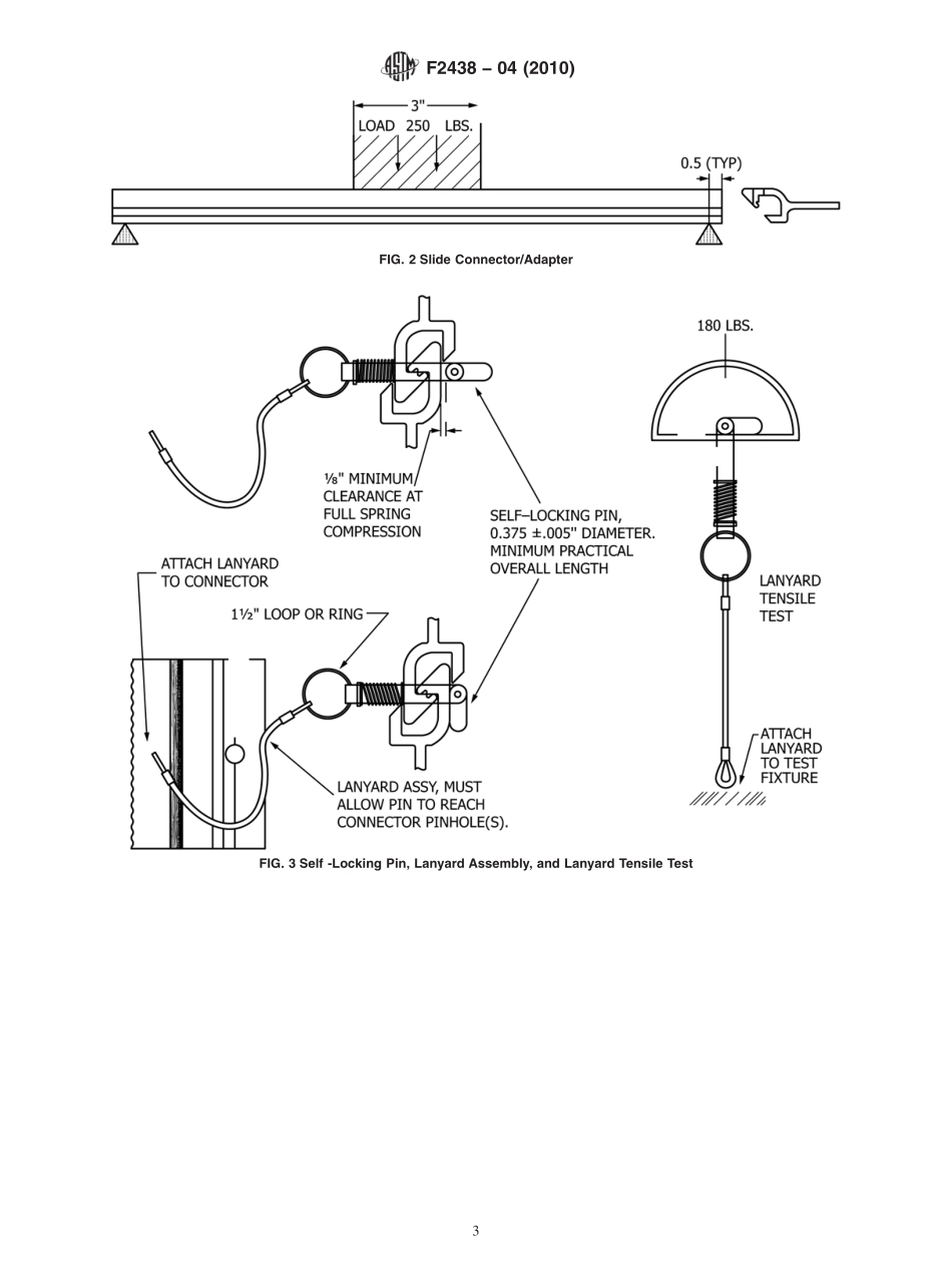
分享
ASTM_F_2438_-_04_2010.pdf
下载文档

ID:191716

大小:222.40KB

页数:5页

格式:PDF

时间:2023-03-04

收藏 分享赚钱
温馨提示:
1. 部分包含数学公式或PPT动画的文件,查看预览时可能会显示错乱或异常,文件下载后无此问题,请放心下载。
2. 本文档由用户上传,版权归属用户,汇文网负责整理代发布。如果您对本文档版权有争议请及时联系客服。
3. 下载前请仔细阅读文档内容,确认文档内容符合您的需求后进行下载,若出现内容与标题不符可向本站投诉处理。
4. 下载文档时可能由于网络波动等原因无法下载或下载错误,付费完成后未能成功下载的用户请联系客服处理。
网站客服:3074922707
TM_F_2438_ _04_2010
Designation:F243804(Reapproved 2010)Standard Specification forOil Spill Response Boom Connection:Slide Connector1This standard is issued under the fixed designation F2438;the number immediately following the designation indicates the year oforiginal adoption or,in the case of revision,the year of last revision.A number in parentheses indicates the year of last reapproval.Asuperscript epsilon()indicates an editorial change since the last revision or reapproval.1.Scope1.1 This specification covers design criteria requirements,design geometry,material characteristics,and desirable fea-tures for oil spill response boom slide connections.Thesecriteria are intended to define minimum mating characteristicsand are not intended to be restricted to a specific configuration.1.2 The specification defines the geometry required to matewith typical Universal slide connectors or Specification F962connectors with web thickness up to 0.3 in.Some veryheavy-duty or PVC connectors may exceed this dimension andnot be compatible.1.3 The values stated in inch-pound units are to be regardedas standard.No other units of measurement are included in thisstandard.1.4 This standard does not purport to address all of thesafety concerns,if any,associated with its use.It is theresponsibility of the user of this standard to establish appro-priate safety and health practices and to determine theapplicability of regulatory limitations prior to use.2.Referenced Documents2.1 ASTM Standards:2F818 Terminology Relating to Spill Response BarriersF962 Specification for Oil Spill Response Boom Connec-tion:Z-ConnectorF1523 Guide for Selection of Booms in Accordance WithWater Body Classifications3.Material Characteristics3.1 End connector and locking pin materials shall be corro-sion resistant in seawater and such other environments as theintended service may require.If dissimilar metals are used,care shall be used in design to avoid galvanic corrosion.3.2 Any material is acceptable for construction of the boomconnector provided consideration is given to such factors asweight,mechanical strength,chemical resistance,flexibility,and conditions of the environment in which it is to be used.4.Design Requirements4.1 The minimum tensile strength of a boom-to-boomconnection shall equal or exceed the minimum fabric tensilestrength specified in Table 1 of Guide F1523.4.2 The connector design shall ensure distribution or trans-fer of the tension member loads from one boom section to thenext through or around the end connector in such a manner thatthe integrity of the joint is not broken at the fabric connectionor any supplemental tension member connection(s).4.3 The connector opening shall be to the right whenlooking at the top of the connector as shown in Fig.1.4.4 The connector or adapter shall not take more than 0.04in.permanent set when a 250-lb load,distributed over 3 in.,isapplied.The load shall be applied at the location that results inmaximum deflection and shall be resisted by supports placed12in.from each end as shown in Fig.2.4.5 An end connector shall be long enough to be compatiblewith the particular boom of which it is a part and not be alimiting member as to the functional freeboard or draft of themembrane.4.6 The design shall include a tethered,38in.diameter,self-locking pin,conforming to the dimensional criteria shownin Fig.3,to resist vertical movement of joined connectors inrelation to each other.4.6.1 The pins overall length shall be minimized and itsends rounded or chamfered so as to minimize wear and tear onadjacent stored booms or injury to boom handlers.4.6.2 The pins spring shall be captured or locked to the pinassembly and shall exert a force on the toggle of between 16and 22 lbs when connectors are assembled.4.6.3 When the pins spring is fully compressed,there shallbe a clearance of18in.between the short end of the toggle andthe mated connector as shown in Fig.3.4.6.4 The toggle shall turn freely and shall latch in eitherdirection.4.6.5 The assembly shall incorporate a ring or lanyard loopof a minimum 112in.diameter for the convenience of pullingthe pin from the boom connectors.1This specification is under the jurisdiction of ASTM Committee F20 onHazardous Substances and Oil Spill Response and is the direct responsibility ofSubcommittee F20.11 on Control.Current edition approved April 1,2010.Published April 2010.Originallyapproved in 2004.Last previous edition approved in 2004 as F2438 04.DOI:10.1520/F2438-10.2For referenced ASTM standards,visit the ASTM website,www.astm.org,orcontact ASTM Customer Service at serviceastm.org.For Annual Book of ASTMStandards volume information,refer to the standards Document Summary page onthe ASTM website.Copyright ASTM International,100 Barr Harbor Drive,PO Box C700,West Conshohocken,PA 19428-2959.United States1 4.6.6 The pin/lanyard assembly shall resist a tensile load of180 lb,placed upon the closed toggle by the test fixture towhich the pins lanyard is attached,without deformation.4.6.7 One pin/lany

此文档下载收益归作者所有

下载文档
你可能关注的文档
收起
展开