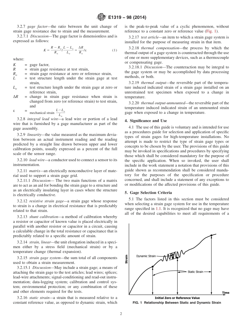
分享
ASTM_E_1319_-_98_2014.pdf
下载文档

ID:169306

大小:320.29KB

页数:11页

格式:PDF

时间:2023-03-04

收藏 分享赚钱
温馨提示:
1. 部分包含数学公式或PPT动画的文件,查看预览时可能会显示错乱或异常,文件下载后无此问题,请放心下载。
2. 本文档由用户上传,版权归属用户,汇文网负责整理代发布。如果您对本文档版权有争议请及时联系客服。
3. 下载前请仔细阅读文档内容,确认文档内容符合您的需求后进行下载,若出现内容与标题不符可向本站投诉处理。
4. 下载文档时可能由于网络波动等原因无法下载或下载错误,付费完成后未能成功下载的用户请联系客服处理。
网站客服:3074922707
TM_E_1319_ _98_2014
Designation:E131998(Reapproved 2014)Standard Guide forHigh-Temperature Static Strain Measurement1This standard is issued under the fixed designation E1319;the number immediately following the designation indicates the year oforiginal adoption or,in the case of revision,the year of last revision.A number in parentheses indicates the year of last reapproval.Asuperscript epsilon()indicates an editorial change since the last revision or reapproval.1.Scope1.1 This guide covers the selection and application of straingages for the measurement of static strain up to and includingthe temperature range from 425 to 650C(800 to 1200F).Thisguide reflects some current state-of-the-art techniques in hightemperature strain measurement,and will be expanded andupdated as new technology develops.1.2 This guide assumes that the user is familiar with the useof bonded strain gages and associated signal conditioning andinstrumentation as discussed in(1)and(2).2The strainmeasuring systems described are those that have proveneffective in the temperature range of interest and were availableat the time of issue of this guide.It is not the intent of this guideto limit the user to one of the gage types described nor is it theintent to specify the type of system to be used for a specificapplication.However,in using any strain measuring systemincluding those described,the proposer must be able todemonstrate the capability of the proposed system to meet theselection criteria provided in Section 5 and the needs of thespecific application.1.3 The devices and techniques described in this guide maybe applicable at temperatures above and below the range noted,and for making dynamic strain measurements at high tempera-tures with proper precautions.The gage manufacturer shouldbe consulted for recommendations and details of such appli-cations.1.4 The references are a part of this guide to the extentspecified in the text.1.5 The values stated in metric(SI)units are to be regardedas the standard.The values given in parentheses are forinformational purposes only.1.6 This standard does not purport to address all of thesafety concerns,if any,associated with its use.It is theresponsibility of the user of this standard to establish appro-priate safety and health practices and determine the applica-bility of regulatory limitations prior to use.2.Referenced Documents2.1 ASTM Standards:3E6 Terminology Relating to Methods of Mechanical Testing3.Terminology3.1 Definitions:3.1.1 Refer to Terminology E6 for definitions of termsrelating to stress and strain.3.2 Definitions of Terms Specific to This Standard:3.2.1 Terms pertinent to this guide are described as follows:3.2.2 capacitive strain gagea strain gage whose responseto strain is a change in electrical capacitance which is predict-ably related to that strain.3.2.3 conditioning circuita circuit or instrument subsys-tem that applies excitation to a strain gage,detects an electricalchange in the strain gage,and provides a means for convertingthis change to an output that is related to strain in the testarticle.3.2.3.1 DiscussionThe conditioning circuit may includeone or more of the following:bridge completion circuit,signalamplification,zeroadjustment,excitationadjustment,calibration,and gain(span)adjustment.3.2.4 compensating gagea gage element that is subject tothe same environment as the active gage element,and which isplaced in the adjacent leg of a Wheatstone bridge to providethermal,pressure,or other compensation in the strain gagesystem.3.2.5 electrical simulationa method of calibrationwhereby a known voltage is generated at the input of anamplifier,equivalent to the voltage produced by a specificamount of strain.3.2.6 free filament gagea resistive strain gage made froma continuous wire or foil filament which is fixed to the testarticle along the entire length of the gage,and which issupplied without a permanent matrix.1This guide is under the jurisdiction of ASTM Committee E28 on MechanicalTesting and is the direct responsibility of Subcommittee E28.01 on Calibration ofMechanical Testing Machines and Apparatus.Current edition approved April 15,2014.Published August 2014.Originallyapproved in 1989.Last previous edition approved in 2009 as E1319-98(2009).DOI:10.1520/E1319-98R14.2The boldface numbers in parentheses refer to the list of references at the end ofthis guide.3For referenced ASTM standards,visit the ASTM website,www.astm.org,orcontact ASTM Customer Service at serviceastm.org.For Annual Book of ASTMStandards volume information,refer to the standards Document Summary page onthe ASTM website.Copyright ASTM International,100 Barr Harbor Drive,PO Box C700,West Conshohocken,PA 19428-2959.United States1 3.2.7 gage factorthe ratio between the unit change ofstrain gage resistance due to strain and the measurement.3.2.7.1 DiscussionThe gage factor is dimensionless and isexpressed as follows:K 5R 2 RoRo/L 2 LoLo5RRo/(1)where:K=gage factor,R=strain gage resistance at test strain,Ro=strain gage resistance

此文档下载收益归作者所有

下载文档
你可能关注的文档
收起
展开